Using notch filters for Rx and TX and extending the range of a notch duplexer
Using notch filters for Rx and TX and extending the range of a notch duplexer (Draft)
I have a six cavity notch duplexer for 70 cm. At the original frequencies, outside the amateur band, the RX and TX notch responses are a mirror of the other, as notch filter responses are asymmetrical, compared to symetrical for band pass..
The mirroring of the responses are achieved by adding a quarter wave line to each cavity in the TX half. Being a quarter wave length, it changes with frequency when the duplexer was tuned about 20 MHz lower from its original frequencies. This was enough to stop the mirroring, making the RX and TX curves much the same; high losses for TX.
The desired TX shape can be restored by adding about 10 mm to the quarter wave lines on the TX side. The length was calculated as the difference in quater wave between the two TX frequencies, in this case about 8 mm. For this duplexer, it was quite easy as the join to the cavity was soldered. The cable was lengthened by adding a 10 mm piece of coax with the cover and shield removed. The join is wrapped with insulation tape. The shield was made from a strip of copper shim wrapped around the cable and soldered to the other cables shield.
The duplexer RX cans on the right, TX cans on the left.
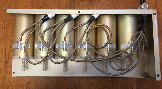
The RX cans showing a simple T join on the coupling loop.

The TX cans showing the extended quarter wave link between the T and the coupling loop.

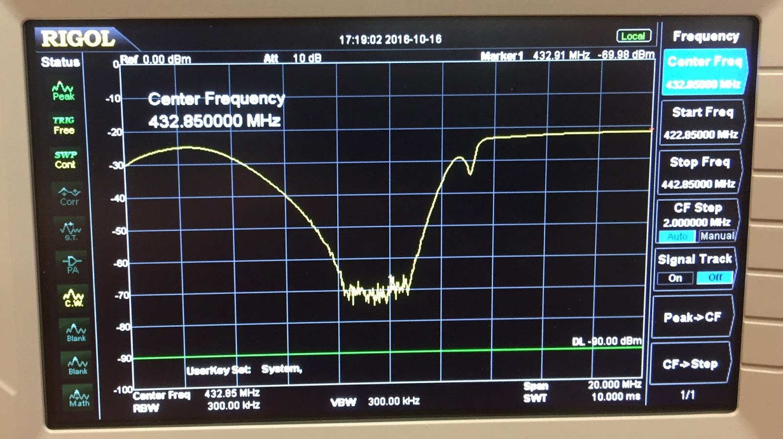
The normal RX response with the low-loss on the low frequency side. The T is connected directly to the cavity.
 The mirrored TX as a result of the quarter wave loop. The low loss side is now on the high frequency side and the High loss on the low frequency side.

I have a six cavity notch duplexer for 70 cm. At the original frequencies, outside the amateur band, the RX and TX notch responses are a mirror of the other, as notch filter responses are asymmetrical, compared to symetrical for band pass..
The mirroring of the responses are achieved by adding a quarter wave line to each cavity in the TX half. Being a quarter wave length, it changes with frequency when the duplexer was tuned about 20 MHz lower from its original frequencies. This was enough to stop the mirroring, making the RX and TX curves much the same; high losses for TX.
The desired TX shape can be restored by adding about 10 mm to the quarter wave lines on the TX side. The length was calculated as the difference in quater wave between the two TX frequencies, in this case about 8 mm. For this duplexer, it was quite easy as the join to the cavity was soldered. The cable was lengthened by adding a 10 mm piece of coax with the cover and shield removed. The join is wrapped with insulation tape. The shield was made from a strip of copper shim wrapped around the cable and soldered to the other cables shield.
The duplexer RX cans on the right, TX cans on the left.

The RX cans showing a simple T join on the coupling loop.

The TX cans showing the extended quarter wave link between the T and the coupling loop.

The normal RX response with the low-loss on the low frequency side. The T is connected directly to the cavity.

Interesting stuff Drew! Graham
ReplyDeleteA 3/4 wave length cavity stub has an enhanced Q that results in a deeper dip.
ReplyDelete73 de Pine, ZS6GST